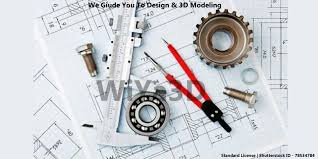
What is Engineering Graphics?
Engineering Graphics is the universal language of engineers. It’s all about visual communication of engineering concepts and ideas through drawings and models. This field teaches the skills necessary to create clear and precise representations of objects and systems, often using standardized methods and conventions.
Here are a few key components:
1. Technical Drawing: This involves creating detailed plans and blueprints using traditional tools like pencils, rulers, and compasses, as well as modern CAD (Computer-Aided Design) software.
2. Orthographic Projection: This method shows different views of an object, like the front, top, and side, to give a complete understanding of its dimensions.
3. Isometric Drawing: This is a way to represent three-dimensional objects in two dimensions, making it easier to visualize the design.
4. Dimensioning: This includes adding measurements to drawings so that the size and shape of each part are clear.
5. Standards and Conventions: Engineers follow specific rules and guidelines to ensure that their drawings are understood universally.
Engineering Graphics is crucial in the design, analysis, and manufacturing of products, ensuring that everyone involved in a project has a clear understanding of what needs to be done.
- Teacher: Dilip Kunte
- Teacher: SEEMA JADHAV
- Teacher: Saylee Lapalikar